Camera Calibration
The purpose of the camera calibration process is to accurately determine the intrinsic parameters of a camera system. This consists of:
- focal length
- lens distortions
- other misalignments during the imaging process.
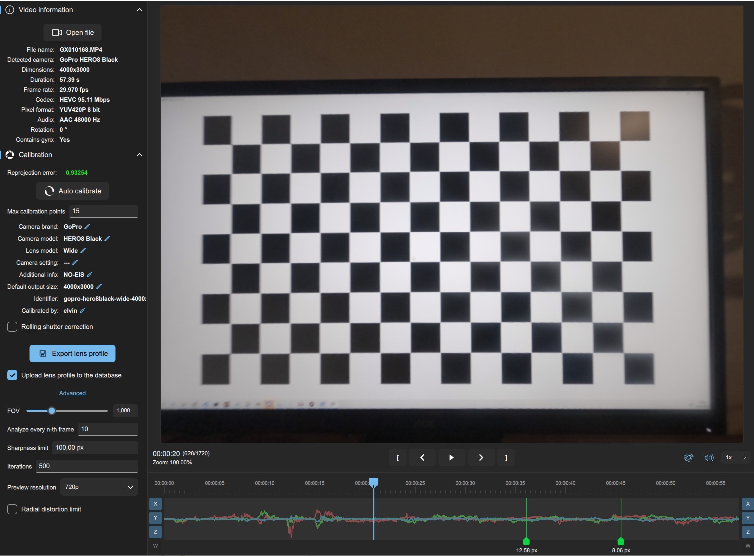
These parameters can be found through Lens Calibration, which consists of imaging a known pattern, and analyzing the resulting footage. The Gyroflow lens calibrator looks like this:
Related to lens calibration is estimating the rolling shutter frame readout time. Most DSLR's and consumer-grade video cameras use a rolling shutter sensors, which introduce warps and distortions in moving footage. It is highly recommended to get an accurate estimate of the rolling shutter before lens calibration and fill in the value in the calibration utility, but it can be done afterwards as well. Please have a look at gyroflow/rollingshutter for an accurate method of measuring rolling shutter or below for an estimated approach.
Video Guide
Nurk FPV's tutorial contains a calibration example:
Getting calibration footage
- Display the calibration pattern on a flat computer monitor, preferably in full screen (available from the lens calibrator utility). You can also print it out if you prefer. In general, larger calibration patterns are preferred since focus will be closer to the focus during actual use, so use your largest screen/monitor. A bright screen with a slightly darkened room works well.
- Select the desired camera settings to calibrate for. Most importantly the field of view/focal length and aspect ratio, if applicable. Framerate and resolution doesn't matter, only if the resolution changes the field of view. Too low shutter speed may also cause undesirable motion blur.
- Record the pattern while slowly moving around to different angles and distances in one clip. 60 seconds is typically enough. Try to avoid motion blur and rolling shutter distortion with slow and steady movements, and make sure the full chessboard is in view. The following angles are recommended for getting distortion information from the full frame:
- Chessboard filling whole frame
- Chessboard seen from distance.
- Chessboard seen at an angle.
- Each edge of video frame aligned with edge of chessboard.
- Corner of chessboard aligned with corner of video.
- Finally, get fast motion for rolling shutter reference/estimation by doing a fast side-to-side yaw motions with the camera. This will produce rolling shutter effect where the lines will be bent, instead of straight.
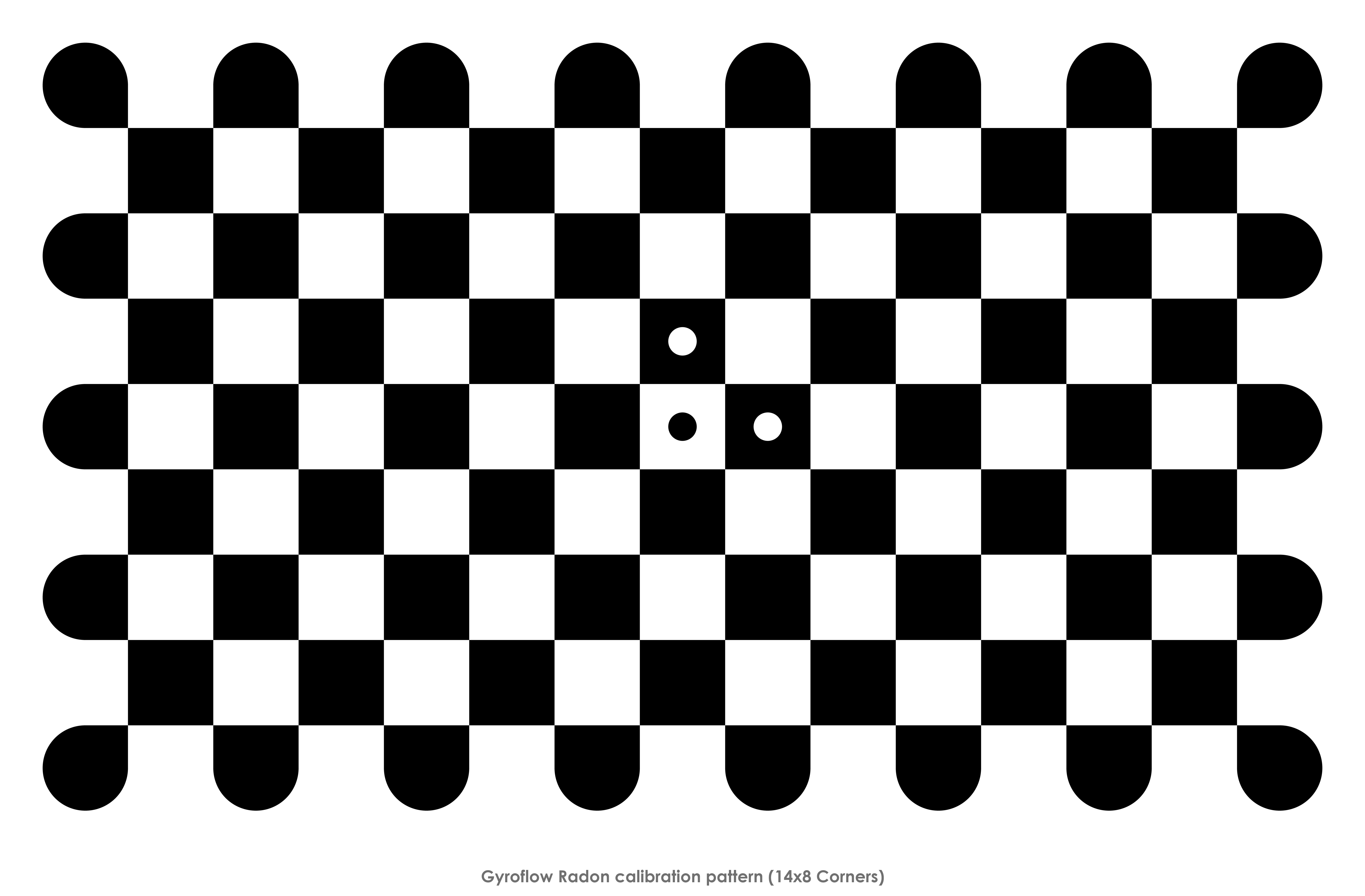
The calibration pattern can be displayed from the calibration utility. Alternatively, the default (14x8 radon) calibration pattern is available here:
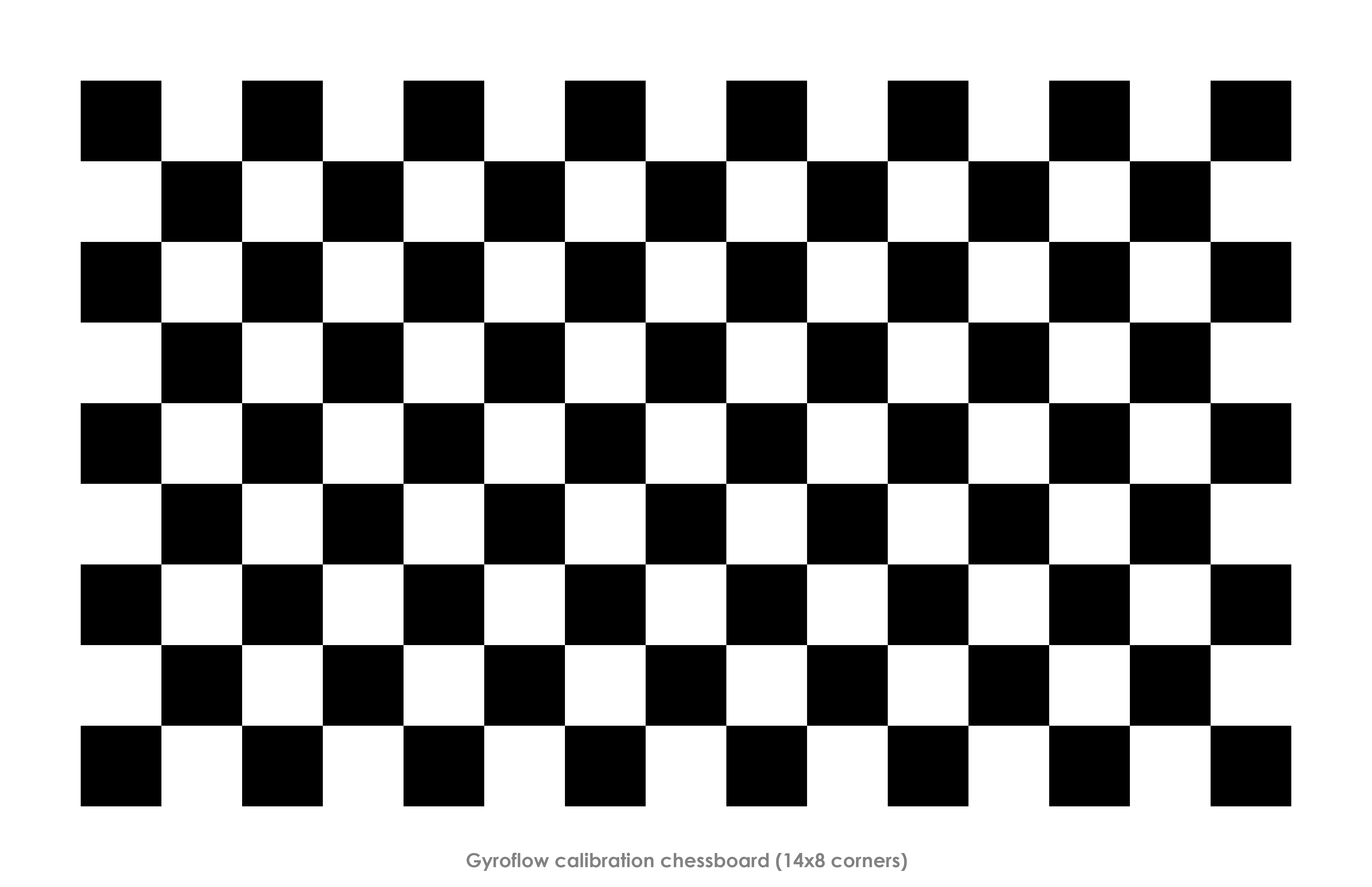
The previous default (14x8 chessboard) calibration pattern is also available below:
Tip: Larger calibration patterns allow for more representative focal distance. Try using the largest screen available, especially with larger lenses.
Creating camera preset
- Start the Gyroflow tool and click
create newunder the lens profile tab. - Open the previously recorded calibration video file.
- Either begin auto calibration or manually add frames using
add calibration pointfrom the timeline context menu. Note: Skip the final fast side-to side motion during this step. - After either the automatic or manual calibration process, check the
reprojection error. This value describes the overall error between the preset and actual lens distortion based on the expected features of the calibration pattern. - After all required frames are added and processed, the straight lines should be straight in the undistorted video. Reprojection error should typically be under 5 (pixels) with excellent calibrations giving values below 1.
- Fill in the preset information and export the lens profile. Try to add all relevant information about the camera/lens combination including field of view setting and lens focal length if applicable.
- If rolling shutter information is known in advance, fill in the frame readout time.
- If a successful calibration was achieved with a low reprojection error and no obvious artefacts, the profile can be submitted with the
Upload lens profile to the databasecheckbox. - You're now ready to use the new lens preset. These are stored as
.jsonfiles.
Estimating rolling shutter
If your calibration video has matching gyro data, the following approach can be used to check the stabilization and estimate the rolling shutter visually. This method only works if the calibration clip had matching gyro data.
An alternative and much more accurate method doesn't require gyro data, but instead requires an Arduino+LED or similar to generate a precise blinking frequency at e.g. 1 KHz. If you have the hardware, this is recommended over the visual method since it's an order of magnitude more accurate. Read more at gyroflow/rollingshutter.
The visual method is as follows:
1. Load the same clip in main window, load the lens profile you just calibrated, sync the gyro with video.
2. Focus on that fast sideways motion part, go to Stabilization -> Rolling shutter correction, and move the slider until the rolling shutter effect is fixed, ie. the lines become straight and are not bent anymore. You may need to reverse the rolling shutter direction.
3. Edit your created lens profile json with notepad, and replace "frame_readout_time": null,, to e.g. "frame_readout_time": 15.5, (15.5ms is an example value). This value will automatically be applied when using this preset.
Additional calibration options
The lens calibrator contains additional options.
Default output size
Radial lens undistortion typically results in the image being stretched more in the horizontal axis (use the FOV slider to see this). For instance, undistorted 4:3 GoPro video:
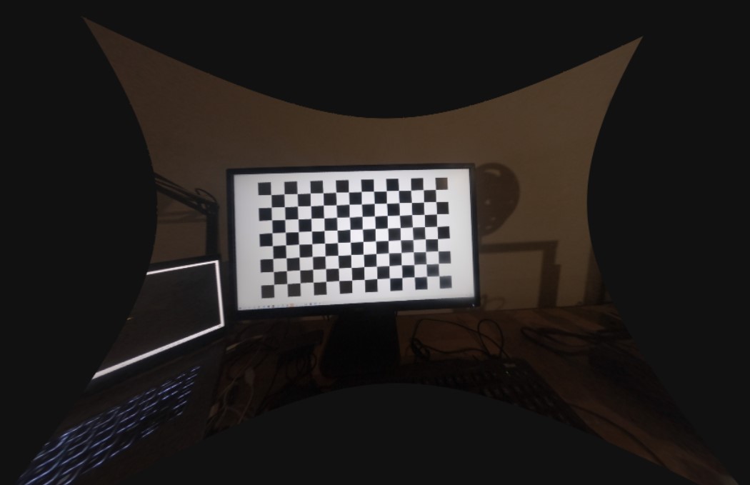
Notice that the area of the valid rectangle is close to a 16:9 aspect ratio as opposed to 4:3. In these cases, the default output size can be modified to a 16:9 one.
For cameras with minimal fisheye distortion, or even with pincushion distortion, the resulting valid aspect ratio is close to the original one. For these cameras, just use the input resolution for the default output size.
Sharpness limit
Sets the minimum required sharpness for the calibration pattern. If the pattern failed to detect due to focus or blurriness, try increasing this limit.